When we draw solid opaque objects such as cubes, the
inside of the cube is completely obscured from view. XNA is unaware of
this, however, and would potentially continue drawing the inside faces
of the cube. This is a waste of processing power because it would
unnecessarily compare and update the inside faces with the depth buffer,
and if the faces at the back are processed before those at the front it
would also actually render them, only to subsequently draw over them
completely with the outer faces of the cube.
You probably won't be surprised to hear that XNA has a solution for this problem—and it's nice and easy to use, too.
XNA can work out whether
each triangle is facing toward us (as the front face of the cube is) or
away from us (as the back face of the cube is). It does this based on
how the triangle is actually rendered, not just how its vertices were
defined, so that, as a triangle rotates, the direction in which it is
facing will change. Those triangles that are found to be facing away
from us are culled
and are not considered for inclusion in the depth or color buffers,
saving all the work that would otherwise have been involved in checking
and updating them.
In order for XNA to be able to
determine the direction in which the triangles are facing, we need to
give our triangle vertices to it in a particular way. When we define the
triangles, we ensure that, when the front of the triangle is facing
toward us, the vertices are provided such that they appear in a
clockwise direction. Figure 1 shows two triangles, one whose vertices are defined in clockwise order (on the left) and the other in counterclockwise order.
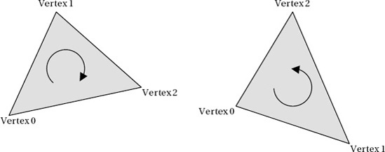
Given these two triangles
to render, XNA will by default display the one on the left, not the one
on the right. If we rotate them around so that their backs are toward
us, the triangle on the left would not display, and the triangle on the
right would appear.
NOTE
Remember that the vertices must appear in clockwise order when the triangle is facing you.
When we define a cube, the rear face is initially facing away from us,
so the triangles would appear to be in counterclockwise order instead.
If the cube were rotated around so that the back face was oriented
toward us, the vertices would then appear to be clockwise, as we need
them to be.
If you look back at the vertices defined for the front face of the cube in Figure 2 in this article,
you will see that both of the triangles have their vertices defined in
clockwise order. This is by design, of course. With our triangles
specified correctly, XNA will automatically ignore those triangles that
face away from us.
The HiddenSurfaceCulling project draws yet another cube, but this time it omits the final triangle from the cube (it tells DrawUserPrimitives
to draw 11 triangles instead of 12), resulting in a triangular hole. We
can look through this hole to the interior of the cube to see exactly
what XNA is drawing for the reverse sides of the cube triangles.
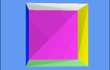
If you run this project, you
will see that the orange side of the cube that contains the missing
triangle shows nothing behind it whatsoever (see Figure 2). Clearly, XNA shows the triangles only when they are actually facing toward us.
Sometimes it is useful to
draw the rear surfaces of triangles, too. If you have objects that are
completely flat and need to be viewed from in front or behind, or if you
have objects that are hollow and whose interior can be seen, we can
configure XNA to render both surfaces of each triangle.
To instruct XNA to render in this way, we need to disable surface culling. Culling is controlled by the GraphicsDevice.RasterizerState.CullMode property, which accepts one of these values: CullCounterClockwiseFace (the default), CullClockwiseFace (the reverse; culls faces that are defined in clockwise order), or None (the value we need here; none of the faces is culled).
The RasterizerState object's properties all become read-only once the object has been set into the GraphicsDevice.
We therefore can't update the properties of the existing object.
Instead, we create a new object, configure it as required, and then set
the whole object into the GraphicsDevice, as shown in Listing 1.
Example 1. Disabling hidden surface culling
// Create and activate a new RasterizerState with a different cull mode.
        RasterizerState rs = new RasterizerState();
        rs.CullMode = CullMode.None;
        GraphicsDevice.RasterizerState = rs;
|
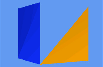
You will find this code present but commented out within the HiddenSurfaceCulling project's Initialize
function. Uncomment it so that it becomes active and then run the
project again. Now you will find when the orange face is toward you that
you can see through the missing triangle into the fully rendered
interior of the cube, as shown in Figure 3.

The important thing to
remember with hidden surface culling disabled is that the interior faces
are being calculated and compared against the depth buffer even when
they are completely hidden from view. When hidden surface culling was
enabled, the interior faces were discarded immediately as XNA knew that
they faced away and therefore didn't need to be checked against the
depth buffer at all.
The final culling mode,
culling clockwise faces, can be useful if you are importing model files that have been defined with
their faces counterclockwise instead of clockwise. Some modeling
applications will define triangles in this way, and this is in fact the
default culling mechanism used by OpenGL. The easiest way to deal with
such objects is to swap the culling mode.
When the culling mode doesn't
match the order with which the vertices have been defined, XNA will
render just the inside of the object, hiding all the triangles that face
toward you. This can result in potentially useful effects, though they
can be visually disorientating. Try modifying the example project code
so that it culls clockwise faces and running it again. You will now see
the inside of the cube, as shown in Figure 4.